Estimating Bone on Bone Forces During FES Rowing
Team Members
- Nicole Stafford
- Lauren Bertoy
- Coline Nantermoz
Table of Contents
Background
Functional electrical stimulation (FES) applies small electrical pulses to nerves that supply paralyzed muscle in order to produce muscle contractions. This method can produce therapeutically useful movements in patients with spinal cord injury who would not otherwise be able undergo these motions on their own. Osteoporosis commonly develops as a secondary complication to spinal cord injuries due to lack of exercise, and this often leads to fracture in the distal femur and proximal tibia. A recent pilot study by Gibbons et al, showed, compared to typical spinal cord patients, a single subject had substantial increases in lower limb bone mineral with long term FES rowing. Dr. Lamabch is currently conducting FES rowing study, on a larger number of participants, at the Palo Alto VA to see if the results from Gibbons et al are more universal.1 The goal of this project is to develop a simple model of a FES rower with a realistic rowing stroke, and use that model to estimate the bone on bone forces at the knee. This will help gain insight into the utility of FES rowing as a way to apply reasonable joint loads and minimize bone loss.
We built and used a simple 1-DOF, planar, 4-body model consisting of a pelvis/HAT, thigh, shank, and foot segment. The model represents the rower in a seated position on the rowing machine, with the seat moving forward or backward along the track and the foot strapped to a platform. A schematic of the system is shown below.

Project Goals
1) Simulate a rowing stroke with a simple 1-DoF model
2) Use a forward simulation to estimate the bone-on-bone forces at the knee to help us answer the following question:
- Can the bone on bone forces during FES rowing realistically match those of walking?
Methods
- Define model parameters
- anthropomorphic measurements (based on existing lower extremity model)
- position of foot relative to axis of motion
- angle of foot relative to axis of motion
- range of motion of each joint
- the thighs, shanks, and feet are each modeled as one body
- Build simple rigid body model in OpenSim
- Ground → (slider x) Pelvis → (pin z) Thighs → (pin z) Shanks → (pin z) Feet ← → (weldconstraint) Ground
- Add hamstring and quadriceps muscles to model
- Apply constant force to upper body
- Use forward dynamics to estimate bone-on-bone forces
- Find excitation pattern that produces realistic rowing motion
- Examine effects of additional muscles
Rower Model
We began by building a rowing model from scratch in C++ as well as stripping down the 10 DOF and 8 muscle model in OpenSim. Building two models from different approaches allowed us to compare results while were constructing our rowing model. At each step, we stopped and compared the joint angles at the hip, knee and angle during a forward dynamic simulation to make sure the two models were the same.
First, we built a simple rigid body model consisting of a pelvis, thigh, shank, foot, and HAT segment. We added a slider joint to connect the pelvis to the ground (and constrain it to move in the x-direction), as well as pin joints at the hip, knee, and ankle. We grouped the two legs together as one, doubling the mass and moment of inertias, and placed it at the center of the pelvis. We then ran a forward dynamic simulation on the model under only the force of gravity.
Next, we constrained the foot such that it would remain stationary throughout the motion, just as the feet remain in the pedal straps on a rowing machine. We placed the foot about 12cm below the pelvis based on a realistic rowing position and ran a forward simulation.
We then added the forces to the model. To account for resistance that the rower experiences throughout the rowing motion, we applied a constant force in the positive x direction. Although this represents the handle force, we applied the force at the pelvis. As the torso is welded to the pelvis, this is equivalent. We applied a force of 150 N based on experimentally obtained power measurements of 50W, and estimates that the pelvis displacement would be 1 m over 3 s.
Next, we added the muscles to our model. Because only the hamstrings and quadriceps are stimulated during FES rowing, we added the hamstrings, rectus femoris, and vasti to the model. We took muscle parameters from the existing 10DOF/18 muscle model, doubling the maximum isometric force to account for both legs. The results from the forward simulation are shown below.
Excitation Pattern
Through trial and error, we found an excitation pattern that resembled a realistic rowing motion. During FES rowing, patients press a button to either stimulate the hamstrings or the quadriceps. The device therefore acts as a switch, with either the hamstrings or quadriceps (in our model, the rectus femoris and vasti) excited at any given point in time. To generate a motion, we simply had to decide where to switch the excitation from quadriceps to hamstrings as the model varies the degree of knee flexion. The excitation pattern below was the one that worked with the pin knee joint, but was producing high knee loads compared to the Gibbons study.

We updated the excitation pattern as we attempted to validate the model.
Validation Process
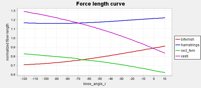
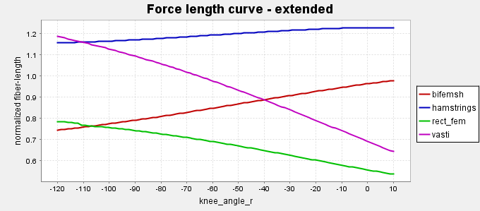
It was important that our model stayed within the tested joint ranges and kept the muscle fiber lengths within the active portion of the force-length curve. To satisfy the first condition, we lowered the feet and tilted the pelvis. We tired a couple different pelvic tilt angles and ultimately settled on 45 degrees because that gave us realistic fiber lengths and was a reasonable pelvic tilt. In addition, we lengthened the hamstrings and rectus femoris to account for the leg being shifted in the middle of the pelvis instead of its normal position.
To evaluate the second condition, we plotted the normalized fiber length through the knee flexion range while the hip was both maximally extended and maximally flexed (within the tested range). The curves are different for different initial position because OpenSim varies the knee angle without taking into account the constraints we set. But in any case, the curves are within the active portion of the force length curve, and therefore the passive forces are not predominant. The hamstrings are especially tight, and the rectus femoris loose: they are not working in the optimal range because of the seated position, which is what we expected.
First Results - Challenges
With our first model we had a discontinuity in our results and hypothesized that there was a wrapping point issue because the muscle was cutting through the knee bone. This was coming from the fact that we centered our unique leg compared to the pelvis, whereas the insertion points on the hip of the rectus femoris and the hamstrings stayed the same.

This was the motion of our rower with the pin joint knee.
We then replaced our pin joint knee with the more anatomically correct knee model from the 10 DOF model and this eliminated the discontinuity in the knee joint forces.
A more realistic handle force
Up to now, we modeled the handle force as constant throughout the cycle. However, an ergometer has a flywheel incorporated in it, so that pulling the handle is hard whereas pushing it back doesn't require force. Thus, we wanted to create a cyclic force, equal to 150N throughout the extension phase and 0 when the rower crunches back.
To create such a step function, we only need 4 points. However, Opensim automatically filters this external load signal and returns huge oscillations:

Adding more data points helps to a certain degree. We still end up with overshoots / undershoots, which are characteristic of a Lagrange interpolation. For an interval of 21 data points, the sweet spot seemed to be one point every 0.05 s.


Adding the Biceps Femoris Short Head
Another challenge we encountered was that a big part of the extension phase was undertaken with the hamstrings activated. This seems counter-intuitive but was made possible by the momentum gained thanks to quads activation and by the fact that the hamstring is a hip extensor (which, because our model has only one DoF extends the knee). The quadriceps were finally active only 0.15 s out of the 1s that took the entire movement. This wasn't corresponding to reality, as the rower activates the hamstrings once he is extended and the hamstrings excitation constitutes around 2/3 of the cycle length.
We decided to add another hamstring muscle, the biceps femoris short head. This muscle only crosses the knee so its activation will help stop the extension and bring back the rower. We found that is effect was not predominant (its optimal force is 3 times smaller than the long head and his fiber length is in the short range in this position). But adding it definitely helped activate the quads longer without hyperextending the knee.
Tweaking the activation pattern
The quads activation process was still too fast compared to reality. Indeed, the forces are high, the vasti having an optimal fiber force of 10,000N. Therefore, we decided to lower the activation: 0.3 for the quadriceps muscles and 0.6 for the hamstrings muscle. In this configuration, the sum of the optimal forces of the 2 muscles of the quadriceps is the same than the one of the 2 muscles of the hamstrings. We also obtain a realistic cycle duration of 1s, with 40% of the time activation of the quads.
Final Results
The final handle force was:

and the excitation pattern:

A forward dynamic simulation produced the following motion:
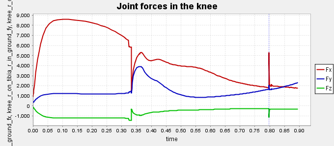
and the following knee loads for one cycle:

These loads are to be compared with the experiment done in the pilot study by Gibbons et al. We obtain a knee load magnitude of almost 4,000N, which, for our 60kg model, represents 3.3 body weights on each knee.

Challenges
- Our knee loads are slightly lower than the ones found experimentally. However, the study was only done on one person and the deviations are pretty high. Being within one standard deviation is already a good validation. However, the shape doesn't match. This could be due to the fact that our activation patterns and our handle force are piecewise constant. We end up with a much more constant knee load, compared to the experiment where it varies continuously.
- The model was created with muscle parameters taken from cadavers of elderly people, rather than data coming from MRI of young healthy people. This is how we tried to recreate the atrophy of the lower limbs' muscles of people suffering from a spinal cord injury. We also lowered the excitations to 0.3 and 0.6. It goes further in this direction, as well as takes into account that 2 electrodes on each face of the leg can't stimulate maximally all the fibers of all the muscles of the thigh. Further study on how much to lower the peak isometric force / the max activation should be done, as it has a direct effect on the magnitude of the knee loads.
Future work
We feel that modeling the muscles of the calf, and thus improving the accuracy of the model, could play a role in the knee loads. Indeed, even without being activated, those muscles produce passive forces as they are stretched, thus loading the joint.
Another axle of study could also investigate the effect of activating the calf muscles instead of the thigh muscles on knee loads and bone density.
Reproducing our results:
This file (readme.txt) explains how to use the different files to reproduce our results.
You can download our final model here.
We used the following excitation pattern in the forward dynamics simulation. The external force is described by this .xml file and this .mot file.
The multiple iterations of the model are available here:
- Bodies + Joints: Stripping down 1018 model Building from scratch in C++
- Adding the Weld constraint: Stripping down 1018 model Building from scratch in C++
After validating that up to this part the 2 models were behaving similarly, we enhanced only the "stripped down" model in xml. - Adding the 3 muscles
- Replacing the pin joint in the knee by a more accurate representation of the patella's role
- Replacing the hamstrings (bifem long head) by the bifem short head
The goal of this replacement was to solve the problem that the majority of the extension part was done when the hamstrings were activated. Having the short head muscle (which only crosses the knee) enabled us not to have to worry about the hip extension action of the long head. However, this muscle is 5 times weaker so it didn't function properly alone. This model was not giving satisfactory results. - Final model: bifem long head + short head
Acknowledgments
We would like to thank Scott Delp and the entire ME 485 teaching team, especially to Calvin Kuo for all the help and guidance with our model.
References
1. Gibbons, RS., McCarty, ID., Gall, A., Stock, CG., Shipppen, J., Adrews, BJ. Can FES-rowing mediate bone mineral density in SCI: a pilot study. Spinal Cord. 52, S4-S5 (2014).
Home: BIOE-ME 485 Spring 2017
OpenSim is supported by the Mobilize Center , an NIH Biomedical Technology Resource Center (grant P41 EB027060); the Restore Center , an NIH-funded Medical Rehabilitation Research Resource Network Center (grant P2C HD101913); and the Wu Tsai Human Performance Alliance through the Joe and Clara Tsai Foundation. See the People page for a list of the many people who have contributed to the OpenSim project over the years. ©2010-2024 OpenSim. All rights reserved.